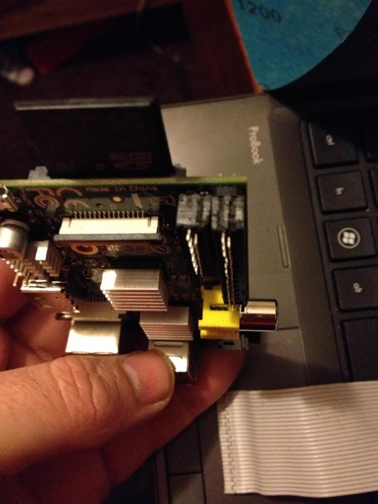
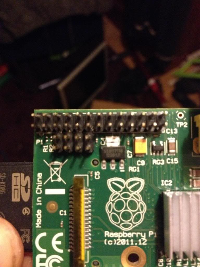
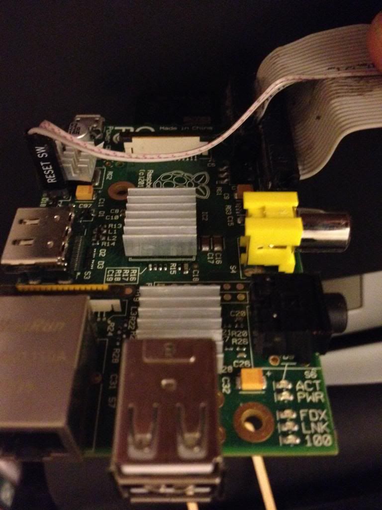
On the Raspberry Pi there is a row of pins called GPIO pins, the block of pins is called P1.
These are on most versions of the Raspberry pi the only input/output pins available.
However on later versions there is a set of 8 pins next to P1 that have no pins soldered in.
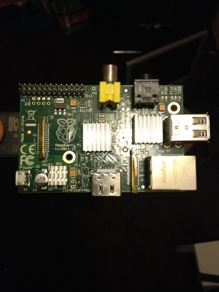
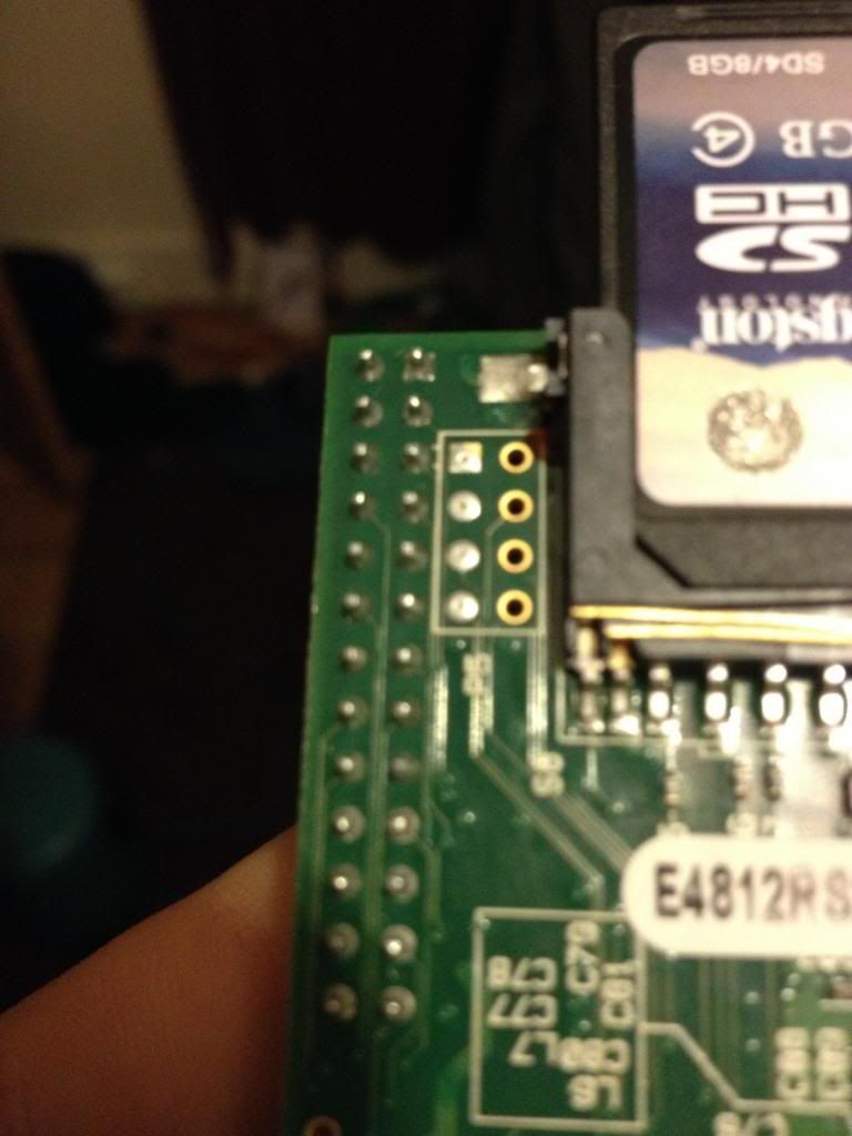
So the first thing to do is remove the solder from this header (P5).
The plug for this header is supposed to be mounted with pins facing downwards. personally I don't understand why I'd want to have cables trailing from the top and the bottom of the boards, to me this seems like a crazy idea. I'd much rather have all my pins accessible from the top. especially when I use the mounting holes in this rev 2 board to screw the board down!
After removing the solder I've added 8 new pins to P5
Next there is a new pin header called P6 on the board, this is a set of pins that a reset switch can be attached to.
So now I need to get a plug to attach to these pins.
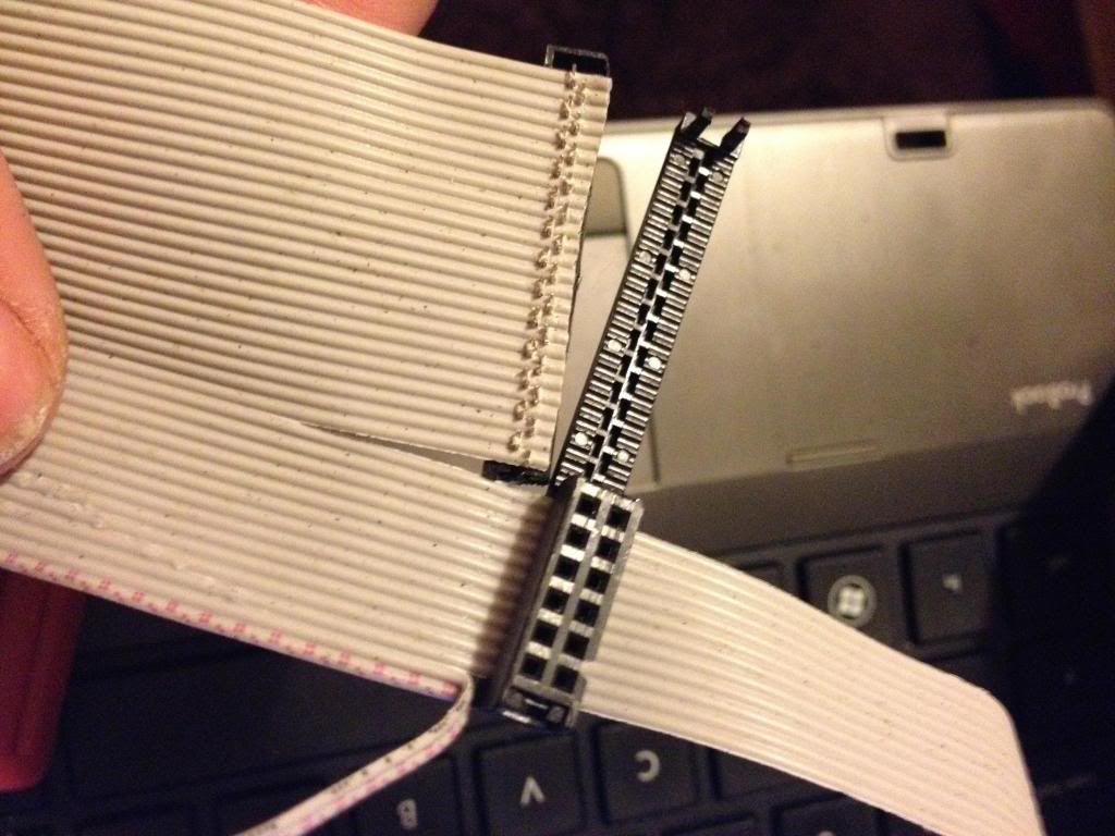
I started with a 44pin IDE cable.
Start by removing the cable from the connector at one end, put that connector that you removed into connector P1. mark the first un-used set of holes, then using a utility knife cut through this set of holes.
This wastes 2 pins in the connector, but don't worry.
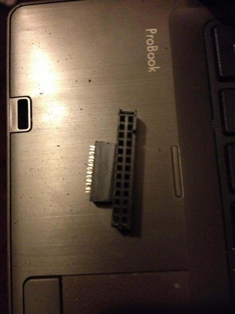
Now using a file or some sand paper you need to sand down the sides of the connector plug so that you can put these two plugs next to each other on the pins of P1 and P5 without them bending the pins.
In the end the plugs should comfortably sit next to each other.
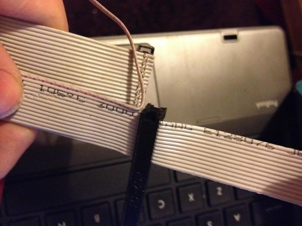
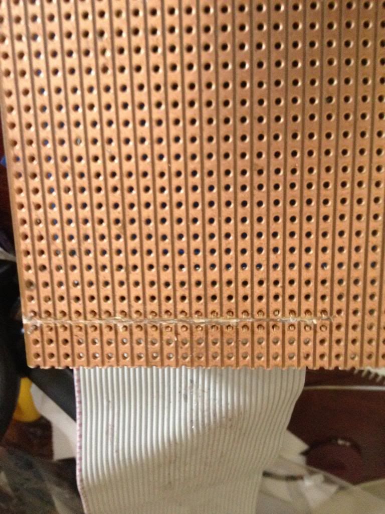
Next take the cable, and divide it to split the cable with 26 pins from end of the cable, lay this across the board and trim the first 26 conductors in the cable so that they are about 1 and a half to two board widths shorter than the rest of the cable, also split the first two conductors away from the bulk of the cable.
Now attach the larger half of the connector that was cut in two to the first 26 pins.

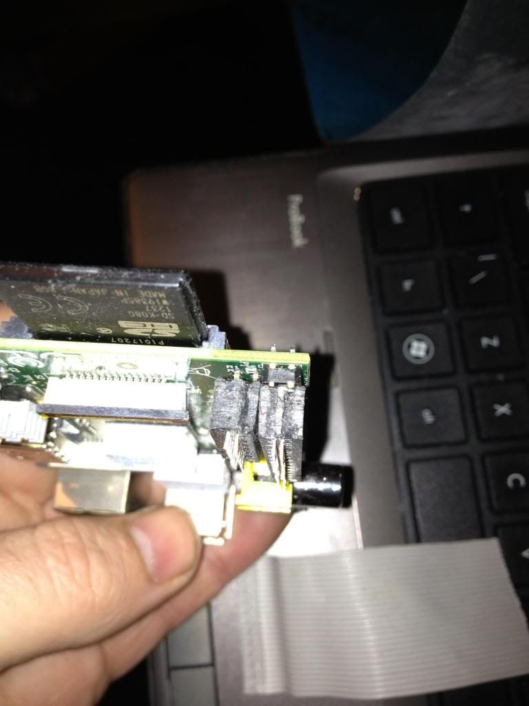
Next turn the cable over, and attach the smaller half of the connector to the remaining part of the ribbon cable, so that it sits diagonally next to the P1 connector.
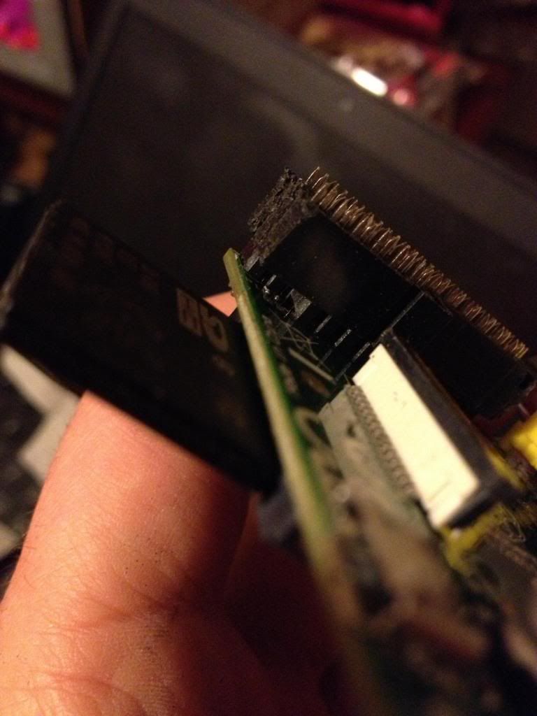
When you fold the cable over, the two plugs should sit next to each other in such a way that they will easily connect to the P1 and P5 headers, (obviously the sides of the connecttor previously sanded away to allow this fit must now face each other!)
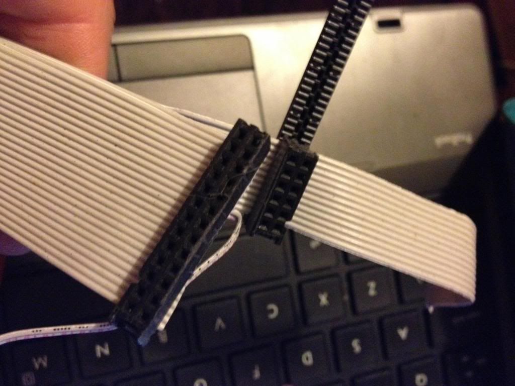
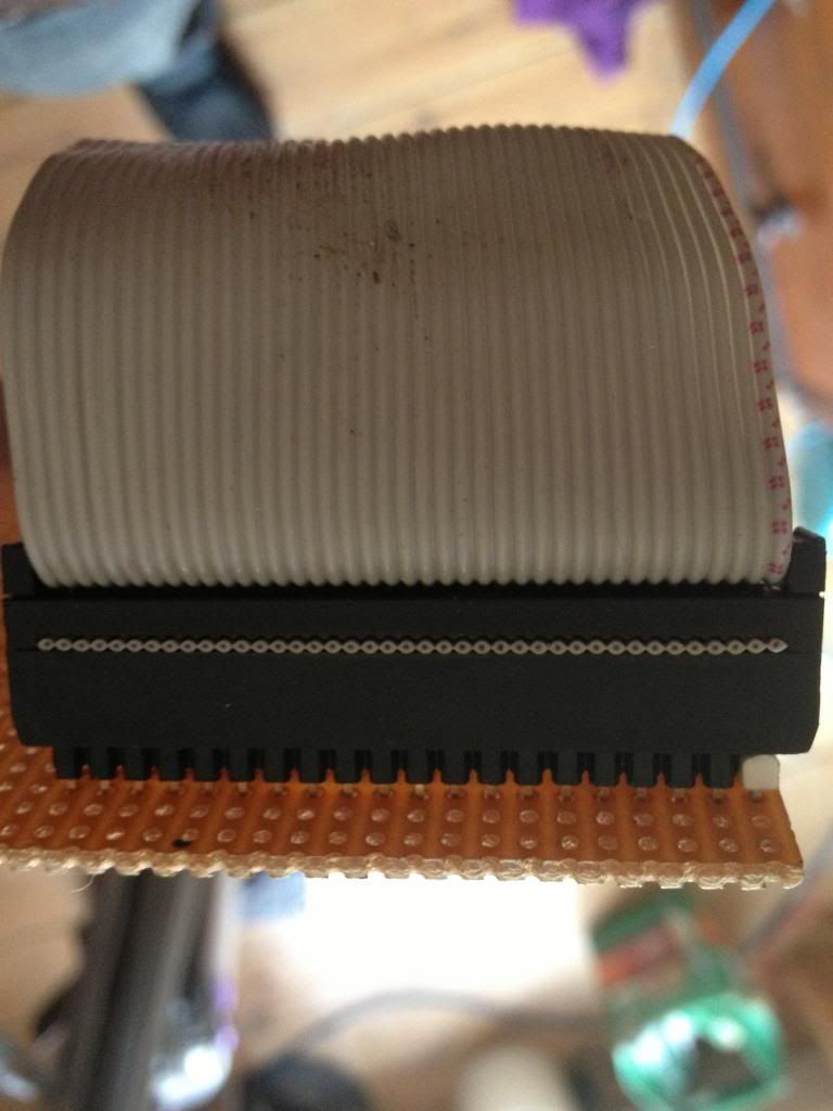
Next cut the cap for the plug and glue over the top of the cable to insulate the terminals that have cut through the insulation on the ribbon cable.

And ensure that both connectors can be attached at the same time.
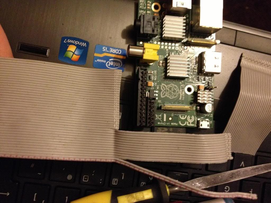
Finally attach a connector to the remaining two conductors in the cable and attach this to P6. I salvaged the connector from an old computer case to it says reset switch, shorting the pins of P6 resets the device so it is apt to use this connector.
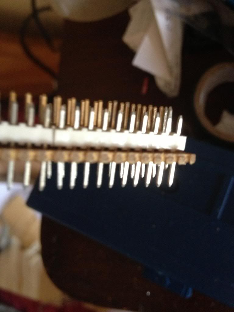
Next using some perf board cut the copper track on 22 rows ready to solder the 44 pin header.
Now solder in the header pins to the perf board.
I've used a 42 pin connector which is black, and used a 2 pin white connector to mark pin 1.
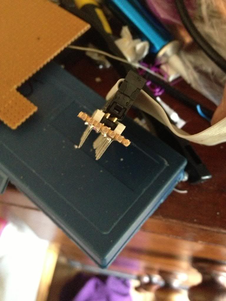
After soldering the cable header pins to the perf board you need to solder some pins that will go into the breadboard.
I used single rows of header pins next to the black connector header.
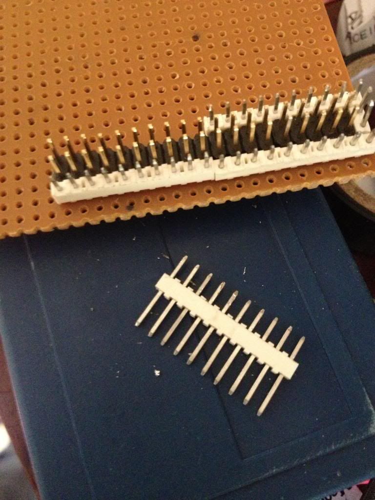
with the pins pushed down into the white block so that they protrude farther out the bottom of the perf board.

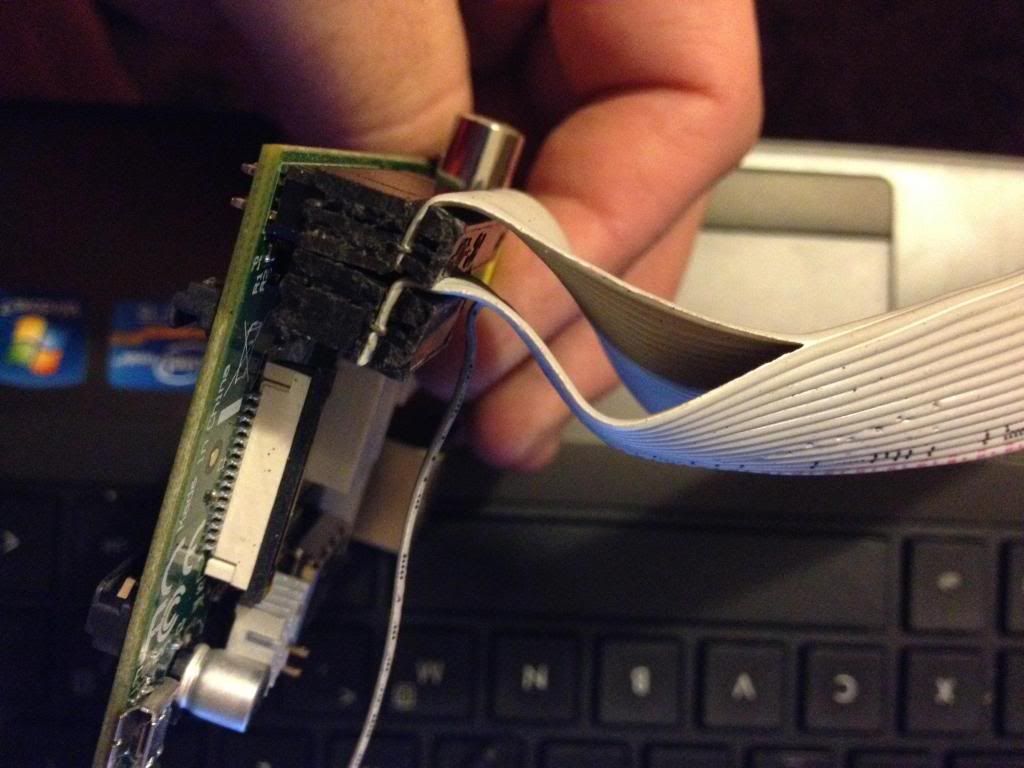
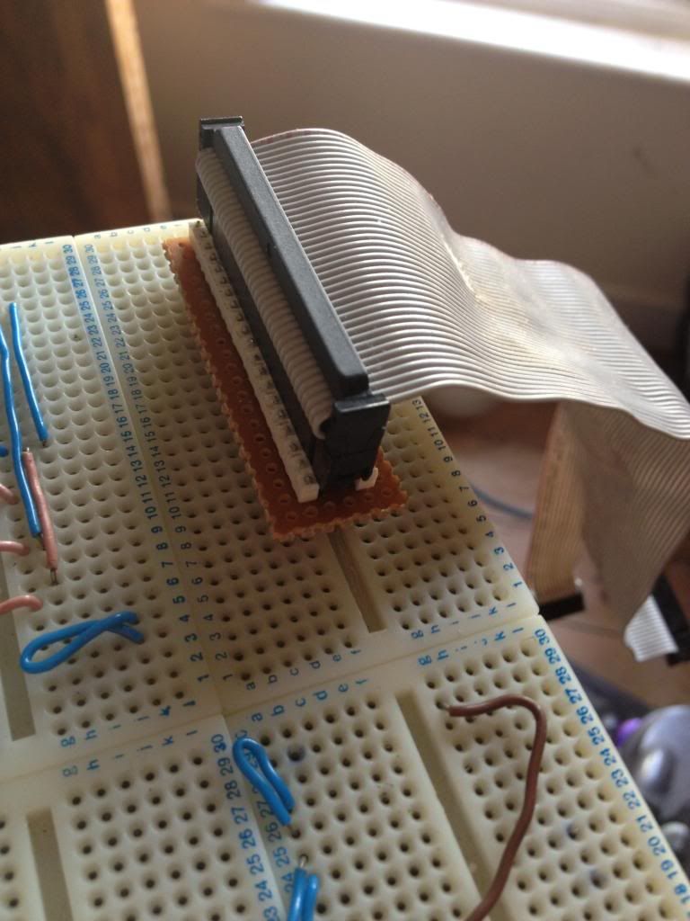
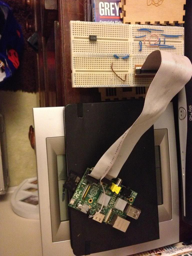
Finally the raspberry pi can be connected to my breadboard.
No comments:
Post a Comment