when we work with binary data we have to have a way to deal with it.
that way of dealing with it is with the use of logic gates.
There are a few basic logic gates.
NOT, AND OR, and XOR.
First NOT
You have two basic states in binary, on or off, if it's not on, it's off, if it's not off, it's on.
the not gate works in the same way as that sentence,
if you put a 1 into a not gate, it's output is 0
if you put a 0 into a not gate, it's output is 1
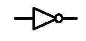
====
0 | 1
1 | 0
AND
The AND gate has two inputs and one output. for the output to be on, ALL inputs to the AND gate must be on, if either one of the inputs is low then the output will also be low.
Think of it like two switches in series, both switches must be on in order for it to work.
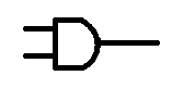
======
0 0 | 0
0 1 | 0
1 0 | 0
1 1 | 1
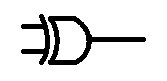
OR
Another basic logic gate is the OR gate. again this gate has two inputs, the out put will be on if either input A OR input B is on.

======
0 0 | 0
0 1 | 1
1 0 | 1
1 1 | 1
XOR
The last basic logic gate is the exclusive OR gate, XOR
With this gate the output will be on if In put A is high, OR if input B is on, but not if input A and input B is on. it must be exclusively A or B that is on, but definitely not A and B.
======
0 0 | 0
0 1 | 1
1 0 | 1
1 1 | 0
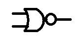
After this we start adding gates together to make more complicated logic gates.
if we put a NOT gate after a AND gate we make a NAND gate we invert the input of a regular AND gate.
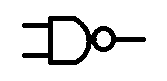
======
0 0 | 1
0 1 | 1
1 0 | 1
1 1 | 0
similarly we can make a NOR gate
======
0 0 | 1
0 1 | 0
1 0 | 0
1 1 | 0
finally we have the Exclusive NOR gate XNOR

======
0 0 | 1
0 1 | 0
1 0 | 0
1 1 | 1
No comments:
Post a Comment