Since then we've used potential dividers to bias amplifiers and provide feedback networks for other amplifiers.
Now I'm going to introduce a very simple circuit, that really going to test that you understand, what voltage, resistance voltage difference and potential dividers are all about!
Potential difference
Now, we mostly think of potential difference as being the difference between a point and ground. when we say what's the voltage there, it's just common sense that we mean, what's the voltage there with reference to 0v, not what's the voltage there with reference to the positive power rail, or negative power rail...
When you think about it, if you have a +9, -9 and 0v power rails, If I say what's the voltage there.
you measure potential difference between 0v and that point and get +3v, if you measured between the 9v rail and that point you'd see -6v, if you measured between the -9v rail and that point you'd measure 12v.
Measuring resistance
The real crux of what we've getting into here is measuring resistance. This can be though of as a how to make your own multimeter.
We should now be comfortable with the potential divider. and what potential difference is.
So I'm going to draw a series of potential dividers, and talk about the voltages that are in use in those circuits.
First, the circuit that I'm going to talk about looks like this:
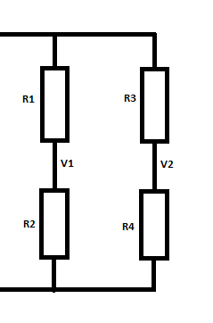
We know that the voltage at any point is relatively easy to find
Voltage = 10v
R1 = 5
R2 = 5
R3 = 5
R4 = 5
We know that the voltage at V1 is (V / R1 + R1) x R2
in this case that's (10 / 5 + 5) x 5
10/10 = 1 multiplied by 5 is 5volts.
We know that the voltage at V2 is 5v also.
So the potential difference between V1 and V2 is zero.
Now lets change the value of R3 to 15
now V1 = 5
but V2 = 10/20 x 5 = 2.5
So the potential difference V1 - V3 is 2.5.
Now is we change the resistor R3 to be 1
V1 still = 5 (that's out reference voltage)
but V2 = 10 / 6 * 5 (10/6 = 1.66666, 1.6666 x 5 = 8.3333
The potential difference is 5 - 8.33333 = -3.3v
This sounds simple and it is.
Lets build a circuit from this.
We'll need a battery.
an analogue volt meter,
3 resistors,
2 bits of wire
1 sharpie.
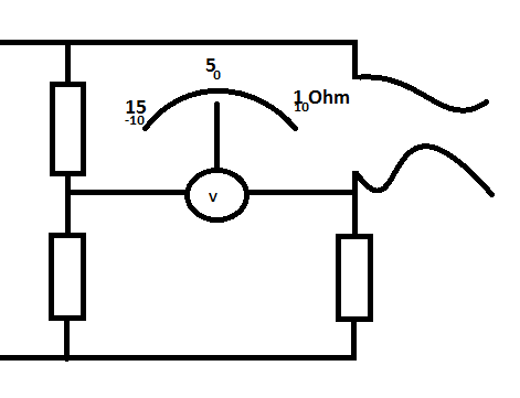
Use the wire to connect resistors of a known value to the circuit, then use the sharpie to draw onto the analogue meters screen to give you calibrated marks.
Alternatively, use a light dependant resistor, and draw on the screen specific points (as measured against another calibrated device) to make a light meter.
Or use a thermistor, in a range of temperatures measured by a mercury thermometer to can have a fully calibrated electronics thermometer.
If you use load cells, (that alter resistance in accordance to the load placed on them) you have electronic scales.
Light, heat water, position of wiper on a potentiometer, if you can get a sensor to return a resistance for whatever environmental input you want, then you can use a whetstone bridge setup like the one above to measure.
No comments:
Post a Comment