What is distortion.
Distortion is the changing of a wave form from one form to another so as to distort it.
Technically speaking, a tone control distorts the signal, a envelop filter distorts the signal, anything that "colours" the signal also distorts it.
but if I stop being a smart ass for a second.
distortion to most people means fuzz.
History of overdrive.
It seems to make sense to me to start at the very beginning, and lets take a look at the physics of what's happening.
Many people try to make a distinction of what type of distortion they are listening to, if it's a hard clipping, or soft clipping, some people thing that an over drive and a distortion are different, they kind of are, but fundamentally it's all the same.
OK, distortion was around long before this, but lets set the scene...
To understand this analogy you;re going to need to know what a green back is.
A green back is a speaker made by the British speaker manufacturing company Celestion in the 60's or 70's.
It was a basic run of the mill speaker, which has gained cult status (and price) with it's inability to handle the power of the signals that people were trying to drive thought it.
Now you might think that from the description above of a basic speaker that's gained notoriety for sounding bad might make you think that I dislike it.
nothing could be further from the truth. the point I'm getting at here is that the magic sound of 60/70 British rock, (think Rolling stones/Yard birds/Led Zepplin) lays a lot in the mechanical and electrical limitations of the time.
Consider how a speaker works,
a coil of wire is suspended in a permanent magnet,
the coil of wire is subject to an electrical current, this makes the coil magnetic, where it will be either attracted to, or repelled from the permanent basket on the back of the cone.
the coil has a paper cone attached to it.
as the coil moves the paper cone moves, this moves air particles, which vibrate through the air and then the air vibrates against our ear drums and happy days we hear sound.
So we get that the coil is moving, and we get that we can turn the volume up and make it move more, but, the coil is attached (with what's called suspension) to the metal frame (spider) in the speaker construction. The size and stiffness of the suspension limits how far that speaker cone can move.
that means that for very large wave forms the speaker will not replicate exactly what is being asked of it.
it tries to reach the point where the signal applied it telling it to go, but excersion limits are met and the speaker cannot move any more.
additionally the suspension on the speaker slows down the cone as it reaches the excursion limit
So the following picture hopes to show you what I mean, I've drawn it on it's side so you can visualise a speaker cone going in and out.
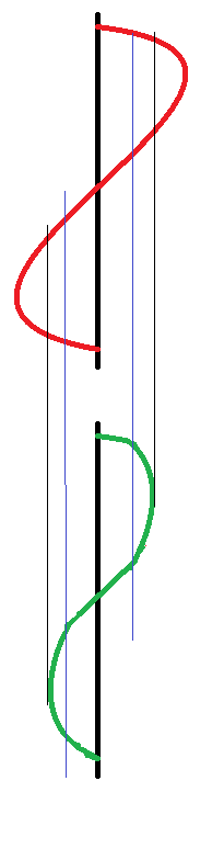
The thick black line is zero, this is where the speaker normally rests.
the red line is the input to the speaker.
you see it rising, the green line (speaker position) moves with it, then we reach the blue line, this is nearing the excursion limits for the speaker, so whilst the red line continues to move, the green line is being slowed by the suspension of the speaker.
The red line continues to rise where it meets the black line, this is the excursion limit the speaker can no longer move at all past this point whilst the red line continues to be at this point the speaker sits as it's maximum excursion position waiting for the red line to fall.
This is, in the most traditional sense an over drive distortion.
the wave is quite smooth, (as the suspension prevents square edges to the sound wave) and as such will sound like a warm fuzz.
It is also possible to get over drive distortion from an amplifier.
Consider the following chart.
the blue wave is what we want. the red wave is what we get
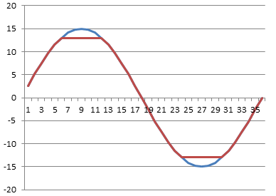
lets say we have an amplifier with supply rails of +15 and -15 volts, you we give the amplifier a 1v / -1v signal and say, amplify that, and set the gain to 15.
What should come out of the amplifier is a smooth wave (the same as went in) with peak values of + and - 15 volts.
but we can't actually drive the amplifier to the supply rail voltages, the most that we could get out is +13 and -13 volts, so the top and the bottom of the votlage is cut off.
This is a much harder clipping sound.
Now that we've listened to loads of music and realised that the classic hot sound of the 60/70s is so desirable what can we do to emulate that?
(clearly we don't want to run our amplifier at that level forever, and the amount of power that you need to put into a speaker cone to reach cone excursion limits makes your show loud, (and perhaps not suited to the venue size you have!)
So you want to fake it.
Well, now that we know what we're trying to fake, it's a very simple matter of finding a way to cut a little from the top and a little from the bottom of an audio wave.
So what we want to do is take a small wave form say 1 or 2 volts then shave a small amount of voltage off of it.
So what we want is a component that can give a low resistivity for small signals, and gradually that resistivity will increase until it hits a limit then it will only allow that amount of signal to pass.
kind of like some kind of flow control.
well, we don't exactly want flow control, but if we look at the diode we have the component that we need.
the following graph shows the voltage and current flow of a regular silicone an germanium diodes as they approach their forward conduction zones:
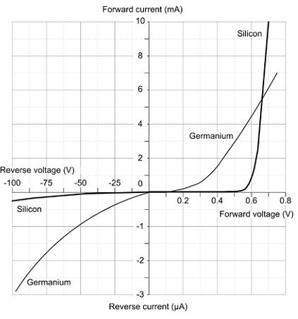
You see that (especially with the silicone diode) there is a gently slope on the voltage vs current graph, this is that component gradually decreasing it's resistance to a signal, until it reaches ~0.65 volts where it begins to conduct, at 0.7 volts the junction inside the diode is saturated and it's in full conduction mode.
So what does this mean for our distortion effect.
Well, quite simply, we wanted a component that we could use to clamp our voltage inside an artificial set of parameters that would mimic the gentle slowing due to suspension and then flat constraint of an over driven speaker. and with a diode we actually have that.
There are two ways of using diodes in a distortion circuit, these are often called hard and soft distortions.
what makes a distortion hard is very angular edges on the wave form when it flattens off, (see the picture of the amplifier distortion above, and soft distortion is more controlled, the distortion still exists, but it's smoother.
not only does the wave look smoother, but it sounds smoother too!.
There are two ways to use diodes to produce this distortion.
First we need to understand the building block that we're using.
two diodes are placed back to back, (and front to front)
this looks like a crazy way to put a diode,-surely they'll just conduct to ground regardless of the signal applied and there will be no output?
Well, no they won't just conduct to ground because as explained above, as the diode is switching on it has a resistance, and even when it's on there is a voltage drop.
So what actually happens is we clamp the signal line to only permit signals within a certain threshold, and limit any larger signals to that threshold.
So now we have a simple model.
for signals under 0.5 volts a diode acts much like an open circuit,
for (silicone) 0.5 - 0.7 volts a diode acts like a resistor with progressively less resistance being applied as the signal rises
for germanium diodes 0.2-0.3 volts acts like a resistor with progressively less resistance being applied as the signal rises
for signal over 0.7 volts the diode acts like a short circuit grounding the circuits and therefore clamping the signal to the activation energy threshold.
now that we have this component block figured out we can look at how to apply to to a circuit.
The first method of connection is to follow the amplifier that is used in the circuit with the component block.
This literally clamps the output to 0.7v, this type of circuit arrangement is suited to either Light emitting diodes or germanium diodes.
the use of silicone diodes produces a quiet hard clipping in this position, mixing a silicone diode and a germanium diode in series for the block can have a positive effect in making this clipping less harsh.
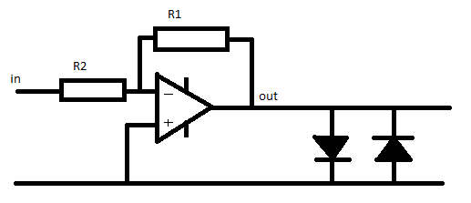
The second way to use this component block is in the feed back network of the inverting amplifier.
we put the network in parallel with the feedback resistor.
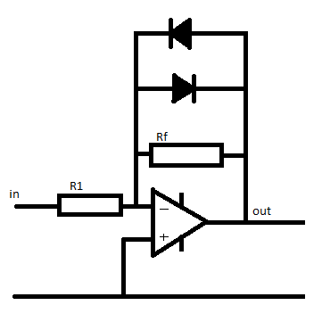
At low signals the diodes act like an infinitely large resistor.
so the value of 1/Rfn = 1/Rf + 1/diodeR(infinity) therefore the total value for the resistor network (Rfn) equals Rf
so if R1 = 100 Ohm, and Rf = 200 Ohms,
Gain = -Rf / R1 so the gain = 2
now as the signal gets larger the amplifier will put out a larger signal, when the output of the amplifier reached 0.55v the diodes are behaving like a resistor.
we'll (for the sake of simplicity) say that the value of this acting resistor is 200 Ohms.
now the feedback network has a resistivity if found by the equation
1/Rfn = (1/200) + (1/200)
so Rfn = 100 Ohms
now the gain of the amplifier is
Gain =-rf/R1
gain = -100 / 100 = -1
so the gain has gone down.
Now the voltage continues to rise to above 0.7 volts, the diodes now act like short circuits.
the resistance of the feed back network a 1/Rfn = 1/200 + 1/0 so Rfn 0
and the gain is
-0/100 which also equals zero.
Remember a gain of 1 is unity.
the output = input x gain.
so a gain of zero actually turns the output off completely.
(but if that were to actually happen the there would be no voltage so the diodes would have infinite resistance again.
thus the voltage is again clamped in the region of the diode conduction threshold.
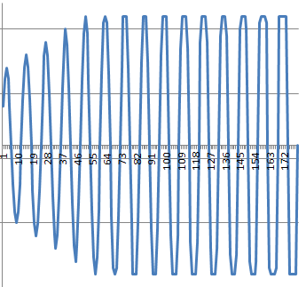
You can see in the graph below what a gradually increasing waveform looks like as it approaches the clipping region.
at the start there is no distortion, as teh wave gets gradually larger the clamping effect of the distortion begins to take effect, you see by the end of the graph the distortion is no longer smooth, the input signal is massive and the clipping is more and more choppy (and will sound worse)
No comments:
Post a Comment