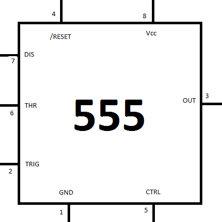
The 555 chip is a timer, it comes in a little black chip form and has 8 legs, the pin outs of the 555 chip are as such:

The functions of the pins are:
1: GND: this is the ground pin and should be connected to the zero volts rail in the circuit.
2: TRIG: the output pin will switch to high when the voltage on this pin goes below 0.5 x Vctrl (the voltage applied to a different pin), If the CTRL pin isn't connected then the output switches high when this TRIG pin goes below above 0.3 x Vcc
3: OUT : this is the out put pin, it's either high or low, there is no middle ground on this one.
4: /RESET: you reset the timing interval with this pin, that slash before the name is not a mistake, it signifies a logical NOT operator, you don't reset this device by adding a voltage to this pin, you reset this device by attaching this pin to zero volts.
5: CTRL: this pin controls the internal voltage divider in the package.
6: THR: this pin controls the output turn off, the output voltage will fall then the voltage applied to the THR pin is greater that the voltage applied to the CTRL pin.
7: DIS: this is called the "open collector output" it can be used to discharge a capacity between the intervals, and is in phase with the output
8: Vcc: the positive supply power pin.
The circuit symbol is a box, with 555 written in the box, there is no set place for wires to come out of that box, and no particular set order that the wires should come out. just draw a box, make a connection to it, and label that connection.
In most circuit diagrams you will find that the RESET and Vcc pin are next to each other (at the top), GND and CTRL are next to each other (at the bottom) DIS, THR and TRIG appear stacked on the left hand side, and the OUT pin appears on the right hand sice of the package on it's own.
lets start looking.
Astable
As a way to remember the states it might be easier to this of astable as unstable! it's not really unstable, (that would conjure up ideas that you didn't know what it would do next) but that the output can't decide exactly where it wants to be.
it puts out a continuous series of pulses with a frequency that is set buy a resistor/capacity network.
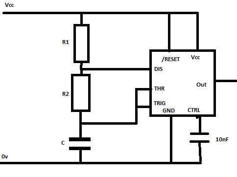
F = 1/(0.693 x C x (R1 + (2 x R2)))
in addition the formula for calculating the "on" time where the output is high is given by the equation:
Ton= 0.693 x (R1 + R2) xC
and the off time is configured as
Toff = 0.693 x R2 x C
So T is Ton + Toff, (that's the total amount of time that the wave form last in a cycle)
and the frequency is defined as F = 1/T (and T = 1/F).
0.693 might look a little weird, but it's the natural log of 2
Ordinarily we actually want to approach this the other way around, we don't generally look at a circuit and say, I see a 555, I see it's connected for astable operation, I see the RC network, now I wonder what the frequency is.
No, ordinarily we are designing a circuit and we say.
I want a specific output wave, and we work from there.
So lets start to show how the design process works:
Our design parameters:
I want a wave form where:
I want a 1000Hz (1KHz) frequency
This means that T = 1/f so T = 0.001 Seconds
I want the wave form to have roughly equal Ton and Toff times, (though since Ton includes R1 and Toff does not, Ton will always be 0.693 x R1 x C seconds longer that Toff
Since we can't have Ton and Toff the same, let's make them pretty close
Ton = 0.0005s (or as close as we can get) Ton = 0.0005001s
Toff = 0.0005s (or as close as we can get) Toff = 0.0004999s (they are within 1000 microseconds)
T = 1ms (that's 0.001 seconds)
So we know that as we want Ton and Toff to be as close to symmetrical as possible, we want R1 to be as small as we can feasibly make the value, without going so small as to upset the overall balance of the circuit. (setting this too low would lead to too much current being drawn) and far from ensuring 50% duty cycle actually makes the duty cycle much less than 50% due to some very weird
We also have equations involving R1 R2 and C for getting values of frequency, we can spend an eternity working on these equations as we alter very slightly one parameter the other two parameters can change. Therefore we should settle on one parameter as soon as we possibly can
The parameter that we need to decide on is what capacitor we'll be using. it makes sense to chose the capacitor, whilst you can for networks of capacitors to get approximate values, it is not convenient, it is far better to chose a capacitor value, and if you then require some weird resistance make a network of resistors to get there!
The value that we'll use for C can be based on what you have.
To get some ball park figures for what C will need to end up at.
so for values of Toff
0.5 seconds (1Hz) C would be in the region of 1uF
0.005 seconds (1Khz) C will be in the region of 1nF
0.000005 seconds (1Mhz) C will be in the region of 1pF
So to recap the equations:
F = 1/(0.693 x C x (R1 + (2 x R2))) = 1/T = 1/Ton + Toff
Ton= 0.693 x (R1 + R2) xC
Toff = 0.693 x R2 x C
Ton = 0.0005001s
Toff = 0.0004999s (ther are within 1000 microseconds)
T = 0.001s
C = 0.000000001F
Toff = 0.0005001 = 0.693 x R2 x 0.000000001
Toff = 0.0005001 = 0.000000000693 x R2
R2 = 0.0005001 / 0.000000000693 = 721000 Ohms (closest standar value is 680,000 Ohms.)
Toff = 0.693 x 680,000 x 0.000000001 = 0.00047124s
Ton = T - Toff = 0.001 - 0.00047124 = 0.00052786s
Ton = 0.00052786 = 0.693 x (R1 + 680,000) x 0.000000001
Ton = 0.00052786 = 0.000000000693 x (R1 + 680,000)
rearranging this we are left with
R1 + 680000 = 761702
so R1 = 81702 (roughly 81K) the closest value is 82K
Ton= 0.693 x (82,000 + 680,000) x 0.000000001
This ends up giving us a Ton time of 0.000528066
This would make Ton + Toff (0.00047124s + 0.00528066) = 0.000999306s
this makes a frequency of 1.006Khz (which is close enough!!)
Once we turn our circuit on it's a Astable circuit, it will switch between the on and off state at the rate set by the Rc network.
Monostable
Another mode of operation for the 555 timer is monostable.
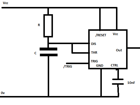
You can imagine this as though it is one of those sprung toy things with the little suckers, you push them down onto a table, and after a while the spring tension is too great for the sucker to keep attached and it springs up.
Just like that toy a monostable 555 timer circuit has a stable state, and an unstable state.
you can put the out put of the timer into it's unstable state position, but after an amount of time (set by an RC network) it will flip right back to it's stable state.
in this configuration there is only 1 resistor and 1 capacitor, the DIS and THR pins on the device are both connected to the junction between the Resistor and capacitor
The trigger pin is either held, or floats high,
at this time the output is off,
when the trigger pin is connected to ground the output switches high, however, this is not it's stable state, so after a short period the output switches back to it's stable state (off) the length of the period is determined by the resistor/capacitor network .
T = 1.1 x R x C
so a 1uF capacitor and a 1Mohm resistor will provide an one time pulse of 1.1 second.
one perhaps shortcoming of this circuit is that once you've pressed trigger, if you press it again during the time that the output is high, nothing will happen.
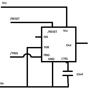
BiStable
The final mode of operation is the bistable the bistable mode means that it has two states where it is stable and can sit indefinitely in either one.
the mode of operation is set with the trigger and reset pins.
both these pins are pulled high, this means that they are connected to the positive power rail with a resistor.
when the trigger pin is pulled to ground the output is set high, it stays this way until such a time as the reset pin is connected to ground then it does off.
This is also called a set/reset flip flop.
No comments:
Post a Comment