Well enter Operational amplifiers, Op amps, comparators, op amp comparators.
they little guys seems to have many names, but they are the same thing, often the same part.
The reason that they have different names is the way in which they are used.
when investigating the long tailed pair we established that the output was (v1 - v2) x gain
The same is true for the operational amplifier.
Most operational amplifiers are extraordinarily high gain amplifiers, however we can use feedback to reign in that large gain.
So, to start with, let's look at the use for infinite gain differential amplifiers.
we talked about the long tailed pair and how the difference between v1 and v2 was amplifiers.
for example,
if v1 = 5 and v2 = 3, and the gain = 4
(5 - 3) * 4 = 8
The output would be 8.
the same is true of comparator amplifiers. except the gain is very very large
(5 - 3) * 1,000,000 = 2,000,000
except the output is not two million volts, because the supply to the circuit is only 12 volts, so the output will be 10 volts.
Yes, ten volts, the maximum output is supply rail voltage - 2 in most chips, (for example the LM741 chip)
This means that we can use the op-amp as a switch, comparing the voltage applied to v1 and v2, (positive and negative,/non-inverting and inverting, or pin 2 and pin3 in the case of the LM741)
where the switch will come on if the signal voltage applied to the non-inverting input goes above the reference voltage applied to the inverting input.
The circuit symbol is a triangle, this is (in black box block diagrams) the symbol for an amplifier, given that the op-amp is a hugely complex circuit packaged nicely in a black box, it seems fitting to use this symbol.
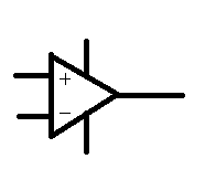
The pin outs are as follows, there are two inputs non-inverting (+) and inverting (-), the the output comes out of the point of the triangle, the two lines going into the top and the bottom are power lines, if there is only one power rail (no split rails) in the circuit then these may be omitted from a circuit design.
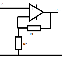
Non-inverting amplifier
We can reduce the gain of the amplifier using a network of resistors. when we made the common collector amplifier we made an inverting amplifier, that was when the signal to the base of the transistor was high, the transistor was in a state of conduction and the signal at the collector was low, (the same as the emitter)
When the signal at the base for the transistor fell the signal at the collector rose as the transistor stopped conducting allowing the supply voltage to exist at the output path.
that was an inverting amplifier.
input signal rise and output signal falling is inverted.
the non-inverting amplifier works in a way where when the input signal is rising the output signal is also rising.
the gain of this amplifier is
Av = 1 + R1/R2
if R1 = R2 then the gain is 2
1 + (50/50) = 2
if R1 = 10k and R2 = 5k
1 + 10k / 5k = 3
so for each 1 volt seen at the input, three volts will be seen at the output
Inverting amplifier
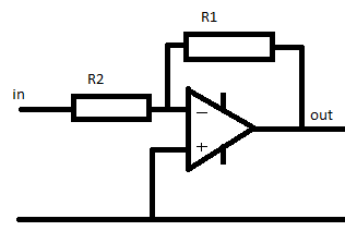
The inverting amplifier is a little different.
(notice that the amplifier has been flipped upside down, and that the negative connection is at the top now.
the gain of this amplifier is
-R1/R2
So in this case if R1 = 10k and R2 = 5k the gain is
-10k/5k = -2
that doesn't mean that the signal is twice as small, it means that it's twice as big, but inverted.
for each 2volts seen at the input there will be 2 x -2 = -4 volts seen at the output
to reduce the signal you'd make R2 smaller than R1
e.g.
-5k / 10k = -0.5
now for each 1 volt seen at the input there is -0.5 volts seen at the input.
Unity gain amplifier
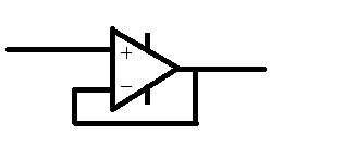
The unity gain amplifier does exactly what it says on the tin the output is at unity with the input, there is no gain.
So you might wonder what's the point.
Well. consider loading.
We know that power is equal to voltage times current, and that voltage is equal to current multiplied by resistance.
Realistically a microphone can supply fractions of volts, with fractions of watts of power.
We're talking in the realms of 0.1 volts (100 millivolts) and a power capability of something like 0.000001Watts
but to make the maths nice and easy, lets say that we have a 10 volt signal, that's capable of supplying 10 Watts
the maximum current available is 1 amp, (w/p = 10/10 = 1)
but what if we're trying to put this into a load of say 5 Ohms,
10 volts and 5 ohms, = 10/5 = 2amps drawn, but we aren't able to supply 2 amps, so the signal is going to be reduced, (the voltages will sag)
we're more likely to see around 7 volts, through that 5 ohm load which will draw out 1.4 amps ,(and 1.4 * 7 = 9.8watts roughly equal to our maximum power.
well a unity gain amplifier has an incredibly high input impedance.
now our 10 volt signal is looking at a 1million ohm load
10/1000000 = 0.00001amps, a tiny amount of power, which means that the signal is not loaded and does not sag.
in addition to this the unity gain amplifier as an incredibly low output impedance, meaning that you can drive very low ohm loads without the voltage getting loaded and sagging.
No comments:
Post a Comment