So, what's actually wrong with this amplifier.
Well, the amplifier is a fender blues junior. these are some (in my opinion) very neat little amps, they have a kind of classic warm blues sound to them, they sound great when they are played at a medium level with a lovely clear signal thought them. They don't do that rocking blues, but they do clean blues sounds really well.
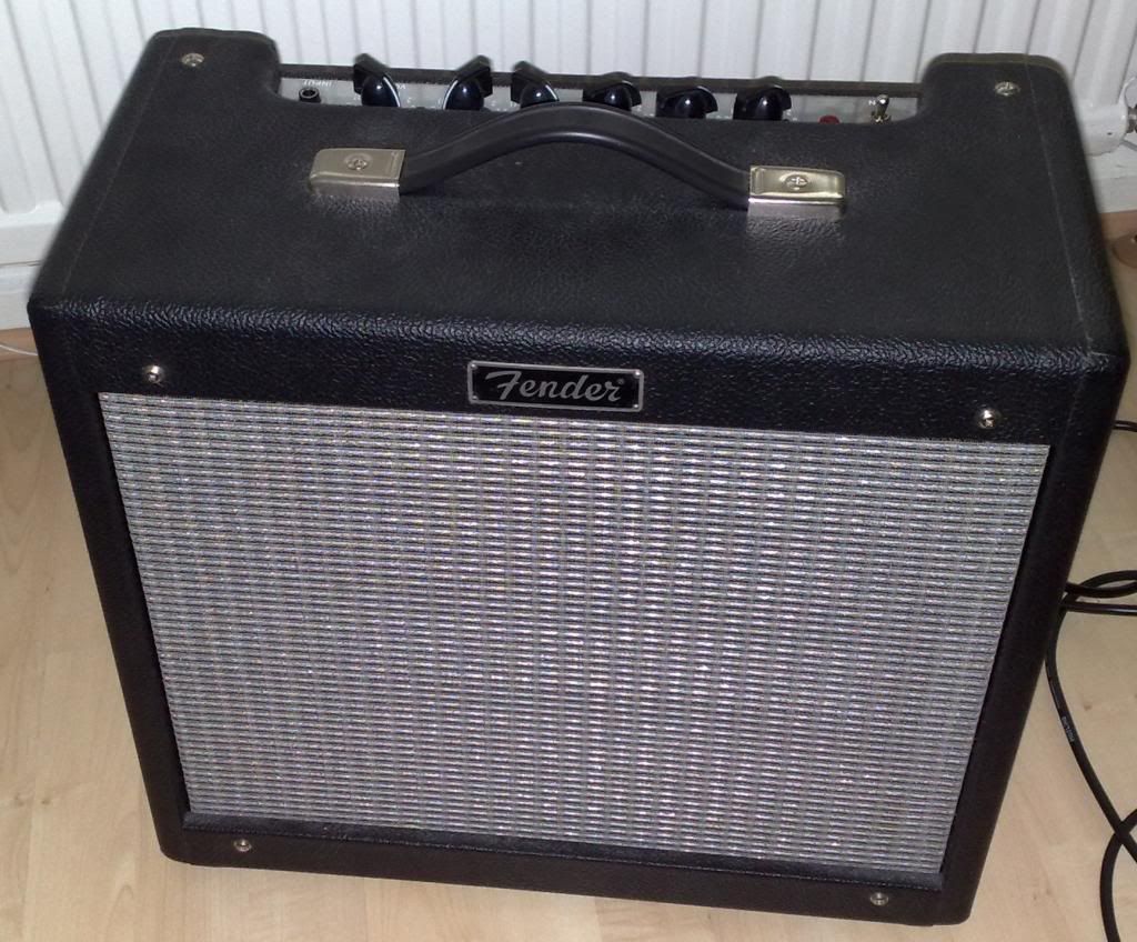
It's come into my hands because the reverb circuit appears to have stopped working.
One of the very cool things about this amplifier from a yes you can fix it point of view is that the circuit diagram actually comes with the amplifier, a quick look at the circuit shows that it's a fairly straight forward reverb circuit.
The signal splits after the pre-amp, and there is a clean channel and a reverb channel, the reverb channel goes to the reverb tank, then after the reverb tank comes back to a recovery amp, then into a mixer circuit where the time delayed signal is mixed to the clean signal to create reverb.
So the first place to look logically is the first component in the circuit.
The reverb tank.
in a guitar amplifier is is most usual to find spring reverb units. the unit works like this.
at the start of the reverb there is an electromagnet, the audio signal goes through the coil of the electromagnet.
that creates a magnetic field that varies in strength according to the music.
the electromagnet acts to move a spring.
the movement at one end of the spring travels through the spring to the other end, where the the springs are contained in wraps of wire.
the spring induces a current in these wraps of wire, (moving magnetic material in a fixed coil induces electricity).
that very small induced electronic signal is then amplifier and mixed back into the original circuit.
the springs work because they are metal and thus conduct the magnetism applied to them as well as the vibration incurred as the coil is energised with the musical signal, in a straight wire this may introduce delay, but the springs, (being as they are springy) bounce around, even after the original signal is recovered the springs will still be bouncing, eventually (as the springs are under tension) the transmission springs movements dampen down until they stop.
It's this dampening that causes the multiple echo sounds that we call reverb.
Back to the amp
In order to test the reverb tank you will need a multimeter.
First unplug the round connector that is at the input side of the tank, and measure the resistivity of the reverb tank, (connect one probe to the centre of the connection, the other probe to the outside.
Make a note of the resistance.
Next unplug the connector on the output side of the reverb tank and measure this.
These reading should be reasonably low. I can't remember off the top of my head what they should be, but one side was reading quite low, not so low that it seemed like it might be shorting out.
The output side was reading very very high, so high that it was likely that there was a break in the coil.
I ordered a reverb tank on-line and replaced the tank. and this amplifier started working again.
30 minutes, and taking out four screws was all it took to fix this amplifier.
No comments:
Post a Comment