To a person that's never seen one before they can be a little strange, it is after all just a little plastic board with a whole heap of holes in it.
But it's the copper tracks underneath those holes that make this useful.
Under the holes there are a series of U shaped coper tracks, when you push a component into a hole it makes contact with one of these tracks. you can then attach another component to another end of this track and you'd connected two components together.
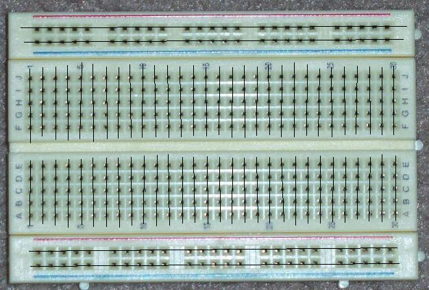
The picture shown above shows the way in which the tracks flow.
At the very top and bottom of the board you have a blue line and a red line, these are to indicate power rails, (what they are normally used for). These run from left to right.
You see how the lines are solid? this indicates that the power rail runs the entire length of the board, if the line has a gap in it, this indicates that the power rail also has a break in it, (thus you can have 8 power rails instead of the 4 on this board, (2 at the top, 2 at the bottom)
The holes in the middle run from top to bottom. the only gap in these rails is the big break in the middle of the board. this big break is the width of a standard small chip, (like a 741, or a 555).
Just as a foot note:
the reason it's called a breadboard is because before this nifty little plastic board with copper tracks was invented people use to use either actual breadboard, (big wooden kitchen chopping boards).
they would use a screw, with a screw cup, then trap wires between the breadboard and brass screw cup to create electrical connecttions.
Even though it's no longer a wooden board, the name has just kinda stuck.
No comments:
Post a Comment