When I was at university we used to program Motorola 68HC11s in either Assembly or C. The development boards that we used in class had 4mm connectors on them allowing us to connect boxes containing switches, or lights, or DACs to the chips using simple instrument leads with 4mm plugs on them.
So I made my own logic output board,
The board consists of 16 inputs, and 16 LEDs, to help identify there, these are coded red and green.
The board is powered by a five volt supply, and has an LED to signify that voltage is present, and a Zener diode to help make sure that the supply voltage does not exceed 5V.
In general you cannot rely on a digital output to have enough current to power an LED.
So I'm using a chip output to turn on a transistor, that transistor is then arranged as an emitter follower, that amplifies the current output from the chip, and provides enough current to light the LED.
How and why this circuit works is covered in the entry immediately prior to this.
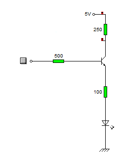
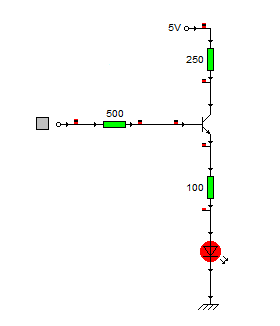
The circuit is that simple circuit, and it's repeated 16 times
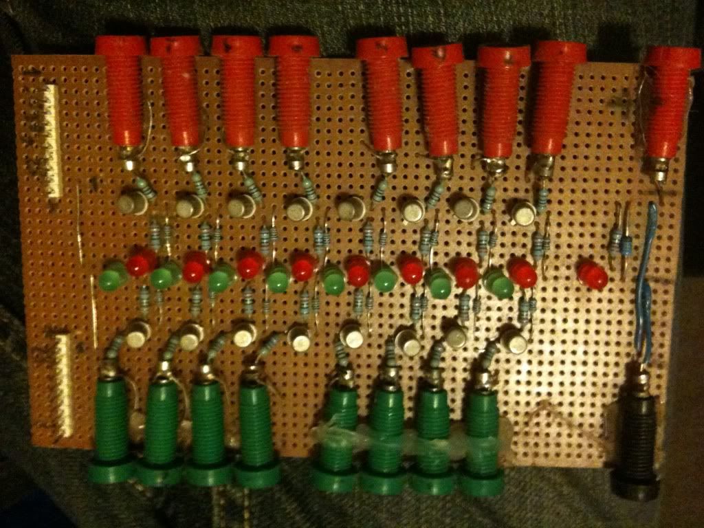
At the bottom of the board there are two ten pin connector, these are 8 logic inputs, and a + 5V supply rail, and a 0v rail.
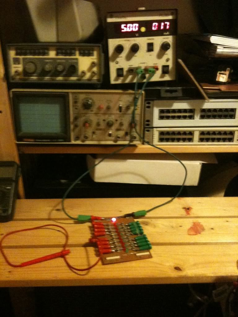
So I can attach my PSU to this logic indicator board (using the voltage inputs and 4mm plugs), and use the board to power my circuit, with nothing more than a simple ribbon cable carrying the supply and signals.
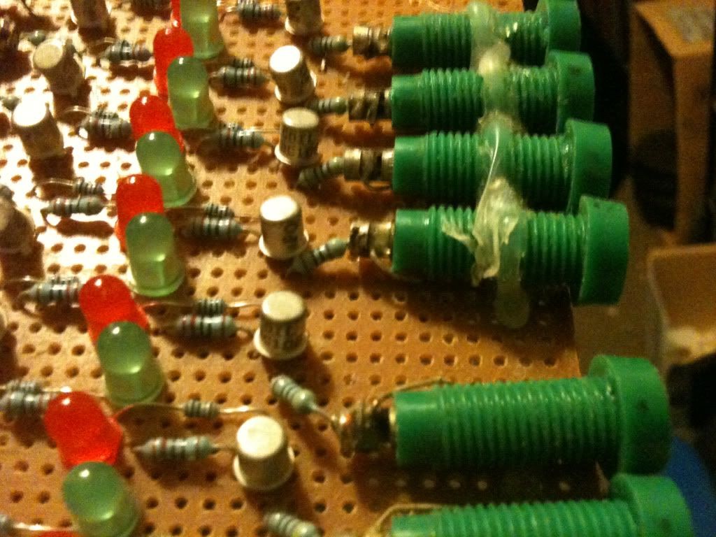
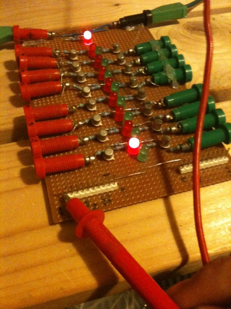
Here are some more pictures of the board, with a probe attached to one of the inputs, and showing a voltage applied to the pin inputs also.
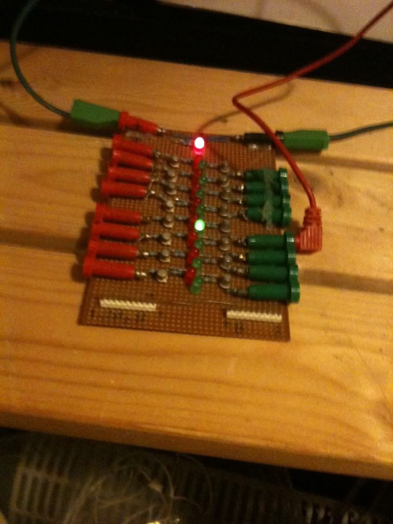
The board powered up:
Logic high applied to an input:
And showing the pin inputs:
so the complete schematic is as follows, this is only one side, but just repeat on the other side.
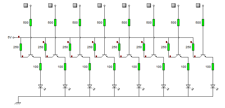
Whether you decide to put a 5v zener diode across the supply, or an LED to indicate that the device is on, is up to you.
The actual connectors are attached to the board by a loop or wire attached, and soldered into the board, then to hold them a little more securely they are also hot glued to the board.
No comments:
Post a Comment