Suffice to say, what electricity is doesn't matter so much as what you can do with it.
I'm going to create a series of blog posts as a kind of electronics 101, the idea being that anyone can start at the beginning, learn about components, and learn how to build up circuits.
Throughout these lessons I'll be making a series of good analogies, and bad analogies.
Resistors
Theory
In Physics things have potential energy when they are sat still, a weight sitting on top of a book shelf has potential energy, if you nudge the weight to the edge it'll fall off, that potential energy has been converted into kinetic energy.
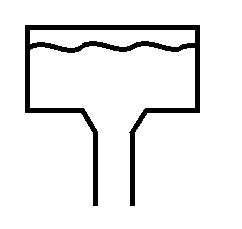
For the purpose of a resistor, think of electricity as like a tank of water, sat on top of a hill, the electricity, like anything is itching to get to the ground, and will take the path of least resistance.
A resistor adds resistance to the flow of electricity.
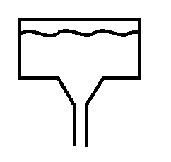
Look at the two pictures, the first shows a tank of water with a small opening, when you think about it you'll see that in this case the water will run down slowly, the narrow channel adds resistance and stops the water just gushing out.
The second picture has a bigger opening, in this case the water just gushes out, you can't stop it because the channel is too wide, the water gushes out with such force that you couldn't just put your hand over it.
There are calculations that you could do, knowing the size of the header tank and the size of the outlet to know with what force the water is pouring through the hole.
In electricity, the size of the header tank is measured in Volts, the size of the pipe or opening is measured in Ohms, and the force that the water pushes is not measured in PSI but is measured in Amps.
Resistance, Voltage and Current
The equation is simple.
The voltage, divided by the resistance is equal to the current.
V/R = I
so say you have a 9v battery, and a 100Ohm Resistor.
9/10 - 0.09A (or 90mA)

Next you might be thinking about about how much power that actually is. (if your resistor can't handle the power it's get hot and fail, sometimes quite spectacularly.)
Voltage, Current and Power
Another electronics law tells us that Power = Voltage multiplied by Current
In the example above the voltage was 9V, and the current dissipated was 0.09A
9 x 0.09 = 0.81W
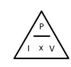
Now less than 1 Watt doesn't sound like a lot, but consider that resistors generally come in 1/8th Watt, 1/4 Watt, 1/2 Watt, you're going to need at least a 1Watt resistor, so it's going to be reasonably large.
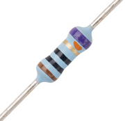
Resistor values
Resistor values are quite easy to remember, once you've been told what the values equate to.
black is zero and brown is one, after that the colours follow the colour spectrum, Red, Orange, Yellow, Green, Blue, Purple, then Grey and white are tagged onto the end. quite why it was done like this with black and brown first, and not just the spectrum colours first then extra ones I don't know...
Anyway,
Black = 0
Brown = 1
Red = 2
Orange = 3
Yellow = 4
Green = 5
Blue = 6
Purple = 7
Grey = 8
White = 9
The last band on the resistor is always Silver, Gold, Brown, Red, Green, Blue, Purple or Grey, these colours relate to the tolerances. (how far off of the stated values the component might be).
Silver = 10%
Gold = 5%
Brown = 1%
Red = 2%
Green = 0.5%
Blue = 0.25%
Purple = 0.1%
Grey = 0.05%
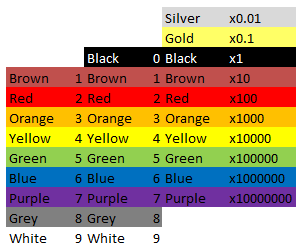
So, if you have a resistor that has colour codes
Red, Red, Brown, Silver
the values are
2 2 * 10 = 220Ohm, +/- 10% -i.e the value is somewhere in the region of 220 Ohm, 198 Ohm - 242 Ohm range (quite a range.)
You might notice that black is missing from the first column, and be thinking how do you write 1Ohm, this should be Black, Brown, Black right? (01 x 1)
Wrong, the correct way to write 1 ohm, is Brown, Black, Gold (10 x 0.1)
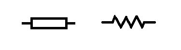
Symbols
Resistors, like all components have a symbol user to indicate them on electronics schematics.
the symbol for a resistor looks like a box (the box does not have a line through it) however you may sometimes find the symbol written as a zig zagged line.
So that about wraps up the humble resistor. There is of course more to learn, there is indeed always more to learn. I'll cover some more advanced stuff with resistors, and the different type of resistors later.
Calculations
As with everything electronics related, sooner or later you run into something maths related.
Even with the simplest of components, maths somehow finds it's way in.
Not to worry though, the calculations concerning resistors are really simple.
Resistors in series
This is as easy as one add one.
When resistors are in series (one linked to the other like a train) you just add all the values together.
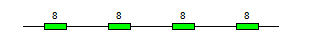
R1 + R2 + R3 + ... + Rn = Rtotal
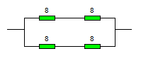
In the circuit above there are 4 x 8Ohm resistors.
8 + 8 + 8 + 8 = 32Ohms.
Resistors in parallel
When you connect resistors in parallel, things get a little more complicated, a mathematician would tell you that it's the sum of the reciprocal of the values of the resistors that makes the reciprocal of the total resistance.
And they would be right, but they'd also likely confuse the hell out of you.
In laymans terms, it's the sum of one over the value of all the components, that makes one over the final value, 1 over this value gives you the total resistance.
(1/R1) + (1/R2) + (1/R3) + ...+ (1/Rn) = 1/Rtotal
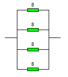
In this circuit the resistors are all arranged parallel to each other and connected differently from the original circuit.
The sum for creating this circuit is
(1/8) + (1/8) + (1/8) + (1/8) = (1/total)
1/8 = 0.125
So writing this out a bit more long hand we have...
0.125 + 0.125 + 0.125 + 0.125 =(1/total)
If you add all of those together you get 0.5
And 1/0.5 = 2
The total resistance of 4 x 8ohm resistors in parallel is 2 Ohms.
Series and parallel connections
Sometimes you're going to want to connect things in a mixture of series and parallel.
You might do this because you want a 1.5ohm resistor, they don't make these but you could connect 2 x 1ohm resistors in parallel
1/1 + 1/1 = 2
1/2 = 0.5
Then add a third 1 ohm resistor in afterwards in series and you get 1.5Ohm.
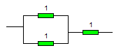
You might want to do this for a completely different reason than getting values that you can't get...
look at this example:
To start with break it down into two halves.
there's clearly a top half (2x 8ohm resistors) and a bottom half that's the same.
So work out the values of those first.
Top half = 8 + 8 = 16 Ohms.
The bottom half also is 16Ohms.
Now they are in parallel to each other
( 1/16) + ( 1/16) = 0.125
1/0.125 = 8
Now you may be wondering why anyone would be such a sadist as to use four components, have to go through that maths when they end up with the same value as just one of those components.
And the answer is power, as in power handling.
If you have a wire that can conduct a certain amount of power (voltage and current), and if you exceed that it'll heat up and melt, then you want to get a bigger gauge wire, you're adding more strands of wire, more paths to go down.
In the example above imagine that they were 10W resistors, but you needed to be able to handle 20W of load, buy arranging two side by side you've doubled that power handling capability to the 20W that you want.
but you've also halved the resistance, so then you add a couple more resistors in series to increase the resistance again.
No comments:
Post a Comment